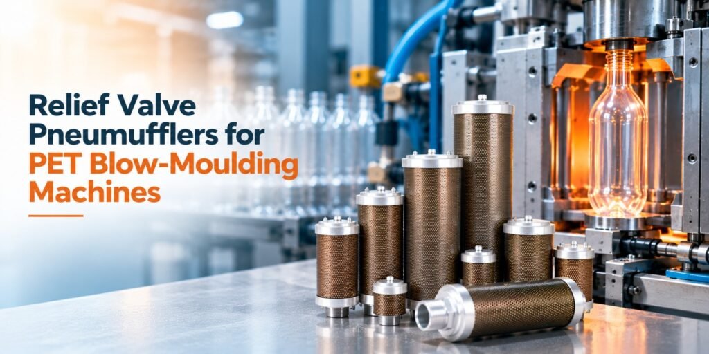
PET bottle manufacturing uses compressed air to form plastic containers into their required shapes.
During production, compressed air must be supplied, controlled and discharged at different stages of the machine cycle.
This creates an important engineering challenge: how to manage pneumatic exhaust noise while maintaining the required airflow and pressure conditions.
A Relief Valve Pneumuffler is one of the specialized pneumatic exhaust products used in applications where exhaust behaviour and pressure conditions require particular attention.
Unlike a basic exhaust silencer, a relief-valve-equipped design incorporates a pressure-responsive feature intended to operate according to its specified configuration.
In PET blow-moulding equipment, where pneumatic operations may involve rapid and repeated air discharge, the correct exhaust arrangement is important for reliable machine operation.
However, the silencer must not be confused with the machine’s certified pressure-protection devices.
This article explains how Relief Valve Pneumufflers work, where they may be used and what engineers should consider before selecting them.
Understanding Compressed Air in PET Blow-Moulding
PET stands for polyethylene terephthalate, a thermoplastic widely used for beverage and other packaging containers.
PET bottles are commonly produced by heating a preform and expanding it inside a mould using compressed air.
The process typically involves several stages.
Preform Heating
The PET preform is heated to a suitable forming temperature.
Mould Positioning
The heated preform is positioned inside the blow mould.
Air Introduction
Compressed air is introduced according to the machine’s forming sequence.
Bottle Formation
The softened PET expands against the mould cavity.
Controlled Exhaust
Air pressure is released as required by the machine cycle.
Mould Opening and Bottle Removal
The formed bottle is removed before the next production cycle.
The exact sequence and pressures depend on the blow-moulding machine design.
High-pressure forming circuits and lower-pressure pneumatic automation circuits may have different exhaust requirements.
Why PET Blow-Moulding Machines Generate Exhaust Noise
Compressed air stores energy.
When pressurized air is released rapidly, it expands and creates turbulent airflow.
This expansion can generate a sharp exhaust sound.
PET production equipment may have several sources of pneumatic noise, including control valves, actuators and designated process-air exhaust arrangements.
The intensity of the noise depends on factors such as:
- Pressure difference
- Exhaust flow rate
- Valve opening characteristics
- Discharge duration
- Exhaust-port geometry
- Frequency of operation
Machines running repeated production cycles can produce frequent exhaust events.
This is where correctly selected pneumatic silencers become important.
What Is a Relief Valve Pneumuffler?
A Relief Valve Pneumuffler combines pneumatic exhaust noise-control functionality with a relief-valve feature.
The exact operation depends on the product’s internal construction and specified pressure settings.
In general, a pressure-responsive valve element opens or changes its flow path when its operating condition is reached.
The silencing portion helps diffuse exhaust air and reduce discharge noise.
For engineers, the important distinction is that the relief feature must be evaluated according to its actual product specification.
A Relief Valve Pneumuffler should not automatically be treated as a replacement for a pressure safety valve, pressure regulator or other required protective device.
Those functions must be determined by the pneumatic system design and applicable safety requirements.
MMHP lists a Relief Valve Series within its PNEUMUFFLER® product range and identifies PET bottling and blow-moulding among relevant applications.
MM Hydro Pneumatics Pvt Ltd
How a Relief Valve Pneumuffler Works
The operation of a Relief Valve Pneumuffler depends on its design.
The following describes the general engineering principle.
Stage 1: Pressurized Air Reaches the Exhaust Arrangement
When the connected pneumatic circuit discharges, compressed air enters the exhaust assembly.
The pressure and flow depend on the valve and machine operation.
Stage 2: The Relief Feature Responds
Where the product includes a pressure-actuated relief mechanism, that mechanism responds according to its specified operating characteristics.
Its opening pressure, capacity and behaviour must be confirmed from the manufacturer’s data.
Stage 3: Exhaust Air Is Released
Air exits through the available flow path.
The exhaust arrangement must accommodate the required discharge without creating unacceptable pressure buildup.
Stage 4: The Silencer Reduces Exhaust Noise
The Pneumuffler’s noise-control structure disperses the exhaust airflow.
This helps reduce the intensity of the discharge sound.
Stage 5: The Circuit Returns to Its Next Operating State
Once the exhaust event is complete, the pneumatic circuit continues according to the machine’s control sequence.
The exact valve reset and exhaust behaviour depend on the equipment design.
Why Relief Valve Design Matters in Blow-Moulding Equipment
PET blow-moulding machines can involve fast and repetitive pneumatic operations.
A relief-valve-equipped silencer must therefore be selected with attention to its operating characteristics.
Pressure Compatibility
The product must be suitable for the pressure conditions of the connected circuit.
Exhaust Capacity
The available flow path must accommodate the required discharge volume.
Repeated Operation
The relief mechanism and silencing structure must suit the expected operating frequency.
Noise Reduction
The exhaust arrangement should achieve the required noise-control objective without excessive restriction.
Material Suitability
The selected construction must suit the operating environment.
These considerations are especially important where different parts of the machine operate at different pressure levels.
Relief Valve Pneumuffler vs Standard Pneumuffler
A standard Pneumuffler primarily provides exhaust noise control through its engineered airflow passages.
A Relief Valve Pneumuffler incorporates an additional pressure-responsive feature.
| Selection factor | Standard Pneumuffler | Relief Valve Pneumuffler |
| Main function | Exhaust noise reduction | Exhaust noise reduction with a relief feature |
| Pressure-responsive mechanism | Not necessarily included | Included according to product design |
| Exhaust flow | Must match application | Must match application and relief characteristics |
| Selection | Flow, pressure, temperature, connection | Flow, pressure, relief specification, temperature, connection |
| Typical consideration | General pneumatic exhaust | Applications requiring the specified relief-valve configuration |
The presence of a relief feature does not make one product universally better than another.
The correct choice depends on the machine’s pneumatic circuit.
Common Problems Caused by Incorrect Exhaust Selection
An incorrectly selected exhaust component can affect equipment performance.
Excessive Exhaust Restriction
If the available discharge path is too restrictive, pressure may remain in the circuit longer than intended.
Incorrect Pressure Rating
A component operating outside its specified pressure range may be unsuitable or unsafe.
Inadequate Flow Capacity
A small exhaust path may not accommodate the required discharge.
Unsuitable Relief Characteristics
A relief mechanism with inappropriate operating characteristics may not perform as required by the circuit.
Contamination
Oil, moisture or particles can affect the silencing structure and potentially the operation of pressure-responsive components.
These problems highlight why a Relief Valve Pneumuffler must be selected using engineering specifications rather than appearance alone.
How to Select a Relief Valve Pneumuffler for PET Machinery
Confirm the Exact Application
Determine whether the product will be installed on a process-air exhaust, pneumatic control circuit or another designated exhaust point.
Identify the Operating Pressure
Verify normal pressure, maximum pressure and any relevant pressure transients.
Determine the Required Exhaust Flow
Use the machine manufacturer’s specifications or appropriate engineering calculations.
Check Relief-Valve Characteristics
Confirm the specified opening pressure, flow capacity and intended function.
Verify Thread and Connection Details
Check connection type, size and installation requirements.
Review Temperature Conditions
The component must be suitable for the actual operating temperature.
Consider Contamination
Oil mist, moisture and particles may influence maintenance requirements.
Verify Safety Requirements
Ensure the exhaust component does not interfere with required pressure-protection systems.
These checks are particularly important for OEM machine design and replacement-part selection.
Maintenance of Relief Valve Pneumufflers
Relief-valve-equipped exhaust components should be inspected according to their manufacturer’s instructions.
Maintenance personnel should watch for:
- Visible damage
- Contamination
- Unusual exhaust behaviour
- Changes in noise
- Restricted airflow
- Leakage where not expected
- Problems with the specified relief function
Before inspection or replacement, isolate and depressurize the relevant pneumatic circuit.
Do not adjust a relief mechanism or modify its construction unless the manufacturer specifically permits the procedure.
If the component fails to operate according to its specification, it should be assessed by qualified personnel.
Why MMHP Relief Valve PNEUMUFFLER®?
MMHP India manufactures different PNEUMUFFLER® configurations for industrial pneumatic exhaust applications.
Its published range includes a Relief Valve Series, and MMHP identifies PET bottling and blow-moulding systems among its application areas.
For PET equipment, product selection should account for the actual pressure circuit, exhaust flow, connection type and required relief characteristics.
The objective is to control exhaust noise while preserving the intended operation of the pneumatic system.
Explore MMHP Relief Valve PNEUMUFFLER® products for further information and application-specific enquiries.
Frequently Asked Questions
1. What is a Relief Valve Pneumuffler?
It is a pneumatic exhaust silencer incorporating a relief-valve feature according to its product design.
2. Where are Relief Valve Pneumufflers used?
MMHP identifies PET bottling and blow-moulding among the applications for its Relief Valve Series.
3. Can a Relief Valve Pneumuffler replace a pressure safety valve?
Not automatically. A silencer with a relief feature should not be assumed to meet the requirements of a certified pressure-protection device.
4. Why is exhaust noise common in PET bottle manufacturing?
Rapid discharge of compressed air can produce high-velocity turbulent airflow and repeated noise events.
5. Does a Relief Valve Pneumuffler reduce backpressure?
Its performance depends on the specific design and flow characteristics. The correct product must be selected for the required exhaust conditions.
6. What should be checked before selecting a Relief Valve Pneumuffler?
Operating pressure, exhaust flow, relief characteristics, temperature, connection type and intended application.
Conclusion
PET blow-moulding machines depend on controlled compressed-air operation.
Rapid and repeated exhaust events can generate significant noise, making correct exhaust-component selection important.
A Relief Valve Pneumuffler combines noise-control functionality with a specified relief feature.
However, correct selection requires careful consideration of pressure, airflow, relief characteristics and the machine’s operating requirements.
Engineers should also distinguish the relief function of the silencer from the separate pressure-safety devices required by the equipment.
Explore MMHP India’s Relief Valve PNEUMUFFLER® range and contact MMHP India for technical product information.